KNX-SA41
Description

Universal switch actuator

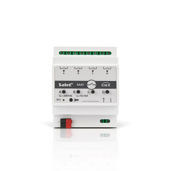
The KNX-SA41 module is a universal switch actuator, which makes it possible to control electrical devices (lighting, ventilation). The telegrams received from various KNX devices (e.g. sensors) are converted, via the module, into concrete actions, such as switching on/off light or fan.

The KNX-SA41 module has 4 relay outputs. Each of them corresponds to one logical channel.

Features:

  • communication with KNX bus via integrated bus connector
  • feedback on the state of module and individual channels
  • reaction of each channel can be defined in case of KNX bus voltage loss and recovery
  • reaction of each channel can be defined in case of mains voltage recovery
  • time functions (flashing, on/off delay, staircase light function with advance warning option and operating time change)
  • logic functions (AND, NAND, OR, NOR, XOR, XNOR)
  • threshold value function
  • safety functions
  • state forcing functions
  • scenes for each of the channels can be called up by using 1- and 8-bit commands
  • manual control of each channel state by using buttons situated on enclosure
  • status LEDs for each channel
  • capability of switching between resistive, inductive and capacitive loads
  • module configuration using ETS software
  • suitable for mounting on DIN rail (35 mm)

KNX-SA41

Price
Product card
KNX-SA41
Information materials
Catalogue
Technical Data
KNX KK
KNX-SA41 data sheet

Description

Universal switch actuator

The KNX-SA41 module is a universal switch actuator, which makes it possible to control electrical devices (lighting, ventilation). The telegrams received from various KNX devices (e.g. sensors) are converted, via the module, into concrete actions, such as switching on/off light or fan.

The KNX-SA41 module has 4 relay outputs. Each of them corresponds to one logical channel.

Features:

  • communication with KNX bus via integrated bus connector
  • feedback on the state of module and individual channels
  • reaction of each channel can be defined in case of KNX bus voltage loss and recovery
  • reaction of each channel can be defined in case of mains voltage recovery
  • time functions (flashing, on/off delay, staircase light function with advance warning option and operating time change)
  • logic functions (AND, NAND, OR, NOR, XOR, XNOR)
  • threshold value function
  • safety functions
  • state forcing functions
  • scenes for each of the channels can be called up by using 1- and 8-bit commands
  • manual control of each channel state by using buttons situated on enclosure
  • status LEDs for each channel
  • capability of switching between resistive, inductive and capacitive loads
  • module configuration using ETS software
  • suitable for mounting on DIN rail (35 mm)